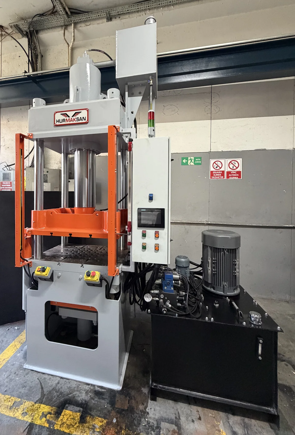
Press frame
Four-column design with induction-hardened, ground column shafts and a hard-chrome-plated main piston.

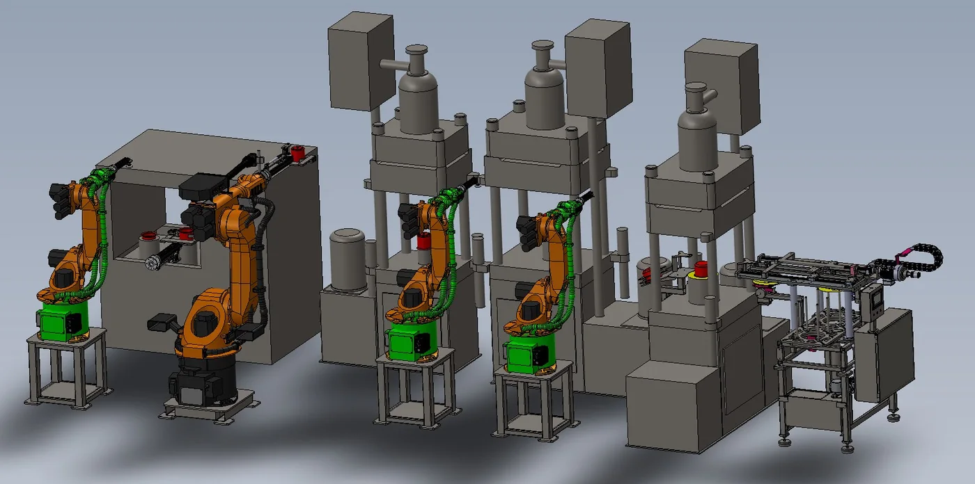
Hydraulic press and robotic transfer
We bring together a four-column press frame, hydraulic power unit, and electrical control cabinet within a technical scope tailored to your part and operation. Let us plan your single-press requirement or a separately engineered robotic production line together.
Application videos
Workshop overview and sample application footage of our four-column hydraulic deep drawing press. The appropriate press configuration and technical scope are defined around your part and tooling.
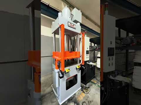
The recording shows an overview of the Hürmaksan four-column hydraulic deep drawing press, operator control panel and hydraulic power unit. The final technical scope is defined for your part and tooling.
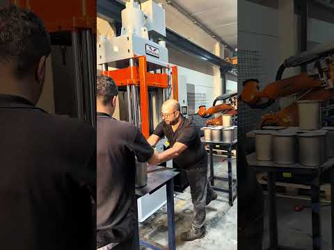
The recording shows a sample operation on the Hürmaksan four-column hydraulic deep drawing press with the press frame, operator controls, tooling and part visible. The technical scope is defined based on your part and tooling details.
Four-column design
The press configuration shown here comprises the frame, hydraulic power unit, electrical control cabinet and specified control equipment. Final technical specifications and delivery boundaries are defined in the project-specific quotation.
Four-column design with induction-hardened, ground column shafts and a hard-chrome-plated main piston.
The press hydraulic power unit and an application-specific machine layout.
Electrical control cabinet for press automation and operator control.
Press automation
The control configuration shown includes the following components. The final configuration for your project is defined during the technical assessment.
PLC control platform for press automation.
Touchscreen panel for machine operation and operator interaction.
Ram position is read from a linear scale and used for position control.
Optical access detection at the machine working area.
Separate project scope
Robotic loading and unloading, press-to-press part transfer and line integration are engineered separately around the part geometry, operation sequence and factory layout. Robots, grippers, transfer systems and the complete production line are not included in the base scope of the single press.
Technical assessment
Please share the following so we can assess the appropriate press and integration scope:
These details support the assessment; technical values and delivery scope are defined specifically for the project after review.
Project archive
Automation archive showing the electrical control cabinet and an existing LORESAN press.
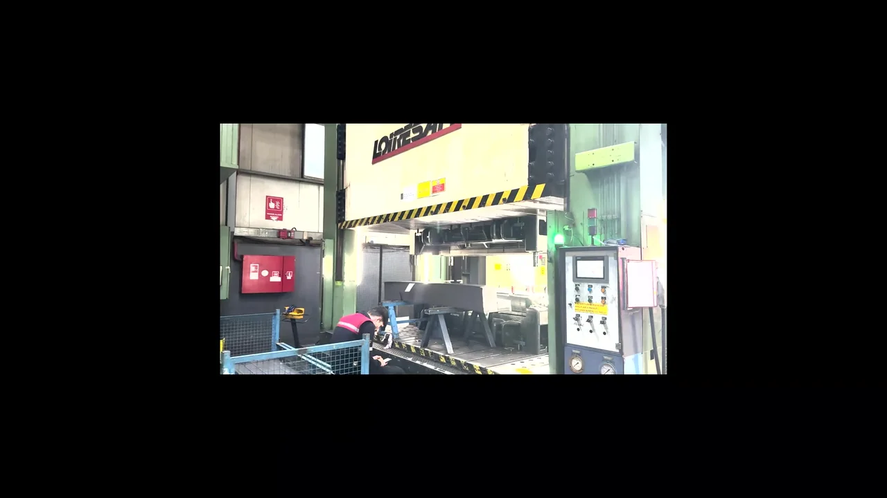
The recording first shows the existing press control cabinet and its internal components, then the operator screen and the LORESAN press with its control console. This archive documents a separate automation project from the four-column press photograph at the top of the page.
We manage the entire process from feasibility to commissioning with engineering discipline.
